Mesh Independence: What It Proves and What It Does Not
Mesh refinement tests spatial discretisation sensitivity. It does not certify the physical truth of the model.
A CFD pressure-drop result changes by less than 2 per cent when the cell count is increased. The analyst calls the answer “mesh independent” and moves on.
That may be useful evidence. It may also conceal three awkward details: only the bulk pressure drop was checked, the refinement missed the valve-seat gap, and both models used the same unsuitable turbulence and boundary-condition assumptions.
Mesh refinement tests one part of CFD credibility: sensitivity to spatial discretisation. It does not prove that the geometry, physics, boundary conditions or comparison evidence represent the real equipment. NASA explicitly distinguishes a numerical result approaching an asymptotic value from approaching the true physical solution.[1]
The practical question is therefore not, “Is the mesh independent?” It is, “How sensitive are the quantities needed for this decision to an appropriately refined family of meshes, and what uncertainty remains?”
The precise question
How sensitive are the quantities needed for this decision to an appropriately refined mesh family, and what uncertainty remains?
What the mesh changes
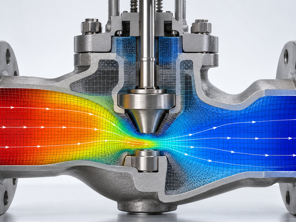
CFD converts continuous governing equations into algebraic equations solved over a finite collection of cells or elements. Cell size, shape, alignment and distribution affect how gradients, boundary layers, jets, separation and recirculation are represented.
A coarser mesh may smooth a narrow jet, under-resolve a shear layer or place too few cells through a restriction. Refinement can reduce the associated spatial discretisation error, provided the numerical method, mesh family and solver convergence behave appropriately. NASA describes a grid-refinement study as repeating a simulation on successively finer grids to assess ordered discretisation error.[1]
A useful study needs a defensible relationship between the coarse, medium and fine meshes. Geometry, wall treatment, refinement regions and numerical settings should remain comparable enough that resolution is the main intended change.
Cell size and distribution
Resolve gaps, boundary layers, jets, wakes and steep gradients where they matter.
Shape and alignment
Control distortion, directional error and numerical behaviour across the family.
Comparable settings
Keep geometry, physics, wall treatment and schemes controlled so resolution is the intended change.
What a mesh-refinement study can demonstrate
A sound study can provide several useful findings.
It can show how much a defined quantity changes as resolution increases. That quantity might be pressure loss between two planes, flow split, force, torque, temperature, wall shear or a local velocity.
The output must be named before the study. A stable average pressure drop does not establish that local wall shear, peak velocity or component force is equally stable.
Results may converge monotonically towards a limiting value, oscillate around it or behave irregularly. The pattern matters. Three similar numbers are less reassuring if they result from cancellation, inconsistent meshes or incomplete iterative convergence.
NASA’s Grid Convergence Index guidance uses Richardson extrapolation to estimate distance from an asymptotic numerical value and presents the GCI as an error band for grid convergence.[1] The ASME V&V 20 standard likewise includes procedures for estimating numerical uncertainty from iterative, spatial and temporal discretisation sources.[2]
Field plots and sectional data can reveal whether refinement changes the mechanism, not just the final number. For example, a fine mesh may resolve a separated jet that attaches differently and changes the downstream pressure recovery.
This is why refinement should target the physics and geometry expected to control the quantity of interest, not merely increase the global cell count.
What it does not prove
The phrase “mesh independent” is often asked to carry more weight than it can support.
A converged mesh family can consistently solve the wrong physical problem. Every mesh may share:
- the wrong fluid viscosity or density;
- an unrealistic inlet profile;
- an outlet inside a recirculation region;
- an inappropriate turbulence or multiphase model;
- omitted leakage, roughness, heat transfer or moving geometry;
- a steady approximation for a materially transient duty.
Mesh refinement addresses numerical solution behaviour. Validation asks whether the model represents reality adequately for its intended use. NIST’s CFD guidance treats model-form uncertainty, input uncertainty and numerical error as distinct contributors to credibility.[4]
Integral quantities often stabilise before local peaks. A pressure drop may change little while the maximum wall shear continues to move or increase as a sharp edge is refined.
The engineer should decide whether the physical question concerns a local peak, an area average, an integrated load or a value at a real measurement location.
Each mesh solution must itself be sufficiently converged. If residuals or monitored outputs are still drifting, the difference between meshes includes iterative error as well as spatial discretisation effects.
Transient CFD adds temporal discretisation. A fine spatial mesh with an excessive time step can still miss a pressure peak or phase relationship. NIST identifies space and time discretisation, iterative convergence and mesh quality among the numerical issues requiring assessment.[4]
Classical extrapolation methods are strongest when the mesh family lies within the asymptotic range, where error reduces in a predictable relationship with mesh spacing. Practical industrial CFD does not always reach that range.
A NASA review notes that three grid levels are typically used, but realistic complex problems can make asymptotic behaviour difficult and expensive to obtain. It concludes that refinement studies remain useful for showing sensitivity, but do not always provide a complete indication of accuracy.[3]
Why cell count alone is a weak measure
Doubling the number of cells does not mean every important length scale has been refined consistently. Adding cells to straight pipes may be less useful than resolving a valve-seat gap, leading edges, the near-wall region and downstream shear layer. The mesh report should describe refinement in important regions, not only total cells.
For three-dimensional unstructured meshes, an effective refinement ratio can be estimated from cell-count changes, but it remains a summary measure. NASA’s guidance allows an effective ratio based on total grid points and problem dimension, while also stressing consistent grid-generation parameters.[1]
Mesh quality must remain controlled across the family. A finer but badly distorted mesh may not be numerically better in practice.
4.5 million cells
Still a weak mesh description if the valve-seat gap, wall region or shear layer remains unresolved.
Worked conceptual example: valve pressure loss
Assume the decision is whether a fixed-open valve has an acceptable pressure loss at one water flow rate. Three systematically related meshes give:
The change from coarse to medium is about 5.5 per cent. The change from medium to fine is about 1.9 per cent. That suggests the bulk pressure-loss result is becoming less sensitive to further refinement.
It does not yet justify the sentence, “The CFD model is accurate to 1.9 per cent.” The difference between two meshes is not automatically an accuracy bound, and both may share other errors.
Before accepting the result, review:
- whether the meshes form a controlled refinement family;
- whether each case has converged to tighter limits than the observed mesh difference;
- whether pressure is averaged consistently on the same planes;
- whether the seat gap, jet and near-wall treatment are adequately refined;
- whether flow rate, water properties and valve opening match the intended duty;
- whether an observed order and GCI calculation are justified;
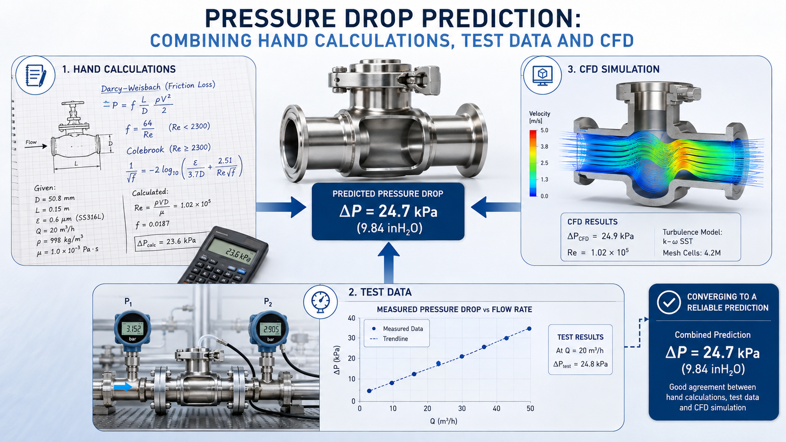
- whether a hand calculation or measured pressure-loss point supports the scale of the answer.
If the local force on the valve element also controls the design, repeat the comparison for force. Stable pressure loss cannot be borrowed as evidence that force is stable.
| Mesh | Cells | Predicted pressure loss |
|---|---|---|
| Coarse | 0.8 million | 21.8 kPa |
| Medium | 1.9 million | 20.6 kPa |
| Fine | 4.5 million | 20.2 kPa |
5.5% change
Bulk pressure loss becomes less sensitive as resolution increases.
1.9% change
This is a mesh-to-mesh difference, not an automatic accuracy bound.
A practical mesh-study sequence
State what will be decided and list the outputs that carry that decision. Include the locations, averaging method, reference pressure and units.
Resolve important gaps, curvatures, boundary layers, jets and wakes. Check mesh-quality metrics against the solver and discretisation method being used.
Use at least coarse, medium and fine levels where the consequence and available resources justify it. Keep geometry, physics, boundary conditions, schemes and convergence criteria controlled. Refine systematically rather than changing several modelling choices at once.
Track residuals, conservation errors and the actual engineering outputs. A low residual is useful, but output stability and balances are also required.
Tabulate each quantity of interest. Plot it against representative mesh size and inspect whether important flow structures move or change character.
Where the refinement family and convergence behaviour support it, calculate observed order, Richardson extrapolation and GCI. Report irregular or oscillatory convergence rather than forcing a tidy percentage from unsuitable data.
Follow the mesh study with sensitivity checks for uncertain boundaries, properties, turbulence treatment, roughness, geometry and time step where relevant.
Compare with an analytical result, benchmark or physical measurement that exercises the relevant physics. A single test point may be enough for bounded screening, but high-consequence or broad extrapolation needs stronger evidence.
Use more precise language than “mesh independent”
Absolute independence is a poor claim because all practical CFD uses finite resolution. Better reporting says exactly what was observed:
The area-averaged pressure loss changed by 1.9 per cent between the medium and fine meshes at the assessed duty. Local wall shear remained more sensitive. This supports use of the fine-mesh pressure loss for the stated comparison, subject to the listed modelling and validation limitations.
That wording is less impressive than a green tick labelled “mesh independent”. It is also more useful to the engineer who must make the decision.
Mesh refinement is an essential verification activity, but it is not a certificate of physical truth. It shows how selected outputs respond to spatial resolution within a defined model. Credibility still depends on the real duty, assumptions, model form, iterative and temporal errors, and appropriate comparison with physical evidence.
Ekyos welcomes enquiries about bounded CFD problem definition, assumptions registers and Simulation Readiness Reviews. Detailed CFD execution remains subject to project-specific competence, method, software, evidence, insurance, conflict and capacity checks. If a result is being accepted mainly because the plots look smooth and two meshes gave similar numbers, a focused readiness review can identify what that evidence supports and what remains unproven.
The area-averaged pressure loss changed by 1.9 per cent between the medium and fine meshes at the assessed duty. Local wall shear remained more sensitive.
Clarify what the mesh evidence supports
A Simulation Readiness Review can separate spatial sensitivity from the remaining model and validation uncertainty.