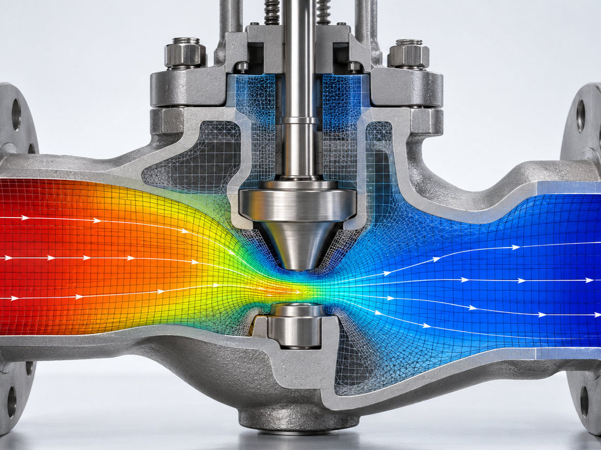
A machine bracket is bolted to a frame. The CAD assembly looks complete, the material data is available and the service load is known. It is tempting to bond every mating face, fix the frame and inspect the stress contour.
That model may solve quickly, but it has quietly replaced a bolted joint with a continuous welded connection. It cannot show interface opening, slip, loss of clamping pressure or the redistribution of load into the bolts. Its stiffness may be wrong before the first contour appears.
Contact, bolts and preload are not decorative model details. Together they define how force crosses an assembly. The appropriate representation depends on the engineering decision, the likely joint behaviour and the evidence available.
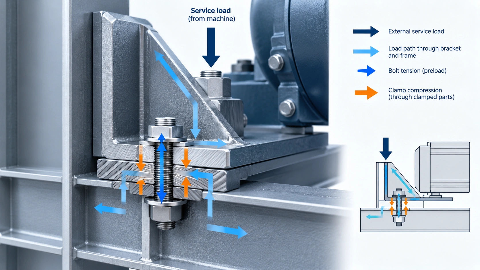
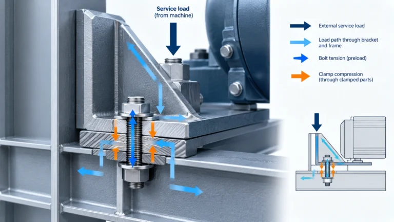
Engineering point: A bolted joint is an assembled load path. Contact state, preload and bolt representation determine what the model is actually solving.
A bolted assembly has several interacting load paths
Before external load is applied, tightening stretches the bolt and compresses the clamped parts. The bolt, plates, washers, gasket and supporting structure form an elastic system. When service load is added, the existing compression can reduce while bolt tension changes by a different amount.
A simple stiffness model treats the bolt and clamped material as springs. NASA’s Fastener Design Manual describes total bolt load as a function of initial preload, bolt stiffness, clamped-part stiffness and external load. It also illustrates how the joint progresses from retained clamp load to separation as external tension increases.[4]
This matters because the statement “the external load is 10 kN, so the bolt receives another 10 kN” is usually too crude before separation. Equally, assuming the bolt load never changes is not defensible. The load split depends on joint stiffness, load introduction, contact state and geometry.
The model must therefore answer the right question. Possible questions include:
- Does the interface remain closed throughout the duty?
- Is shear transferred by friction, bolt bearing, dowels or a mixture?
- How much does bolt force change under the service load?
- Does local separation alter alignment or sealing?
- Is global assembly stiffness sensitive to preload?
- Are local bearing, thread or under-head stresses required?
These questions do not all need the same model.
Contact changes stiffness as the load is applied
A bonded interface transfers tension and shear everywhere across the selected faces. Real dry contact normally transfers compression, may separate in tension and may resist tangential movement through friction until slip occurs.
That difference can change:
- the effective span of a plate or bracket;
- the distribution of contact pressure;
- local bending near a joint edge;
- the balance between frictional shear transfer and bolt bearing;
- bolt force and bending;
- deflection, alignment and natural frequency.
Contact analysis is also numerically demanding. NAFEMS classifies contact, gapping and sliding as problems with distinct physical attributes, numerical solution techniques and geometric representations, and provides benchmark cases specifically for checking them.[2] A solver reaching equilibrium is therefore only the beginning of the review.
Friction is an input, not a convenient tuning knob
Friction may govern whether a joint sticks or slips, but its value can vary with material pairing, finish, coating, lubrication, contamination, pressure and service history. A single guessed coefficient should not be presented as a measured property.
If the conclusion depends on friction, use a justified range and report the sensitivity. Where slip must be prevented for safety or function, the physical design may need positive shear-transfer features rather than reliance on an uncertain model input.
Contact pressure deserves its own checks
A plausible-looking pressure plot can still be sensitive to mesh density, contact formulation, initial gaps, surface normal direction and penalty stiffness. Review integrated contact force as well as local peaks. Check whether the pressure footprint and force balance make physical sense.
Refining the entire assembly is rarely efficient. Local refinement should follow the contact gradients and the decision-relevant region, with a separate check that the reported quantity is converging.
Bolt representation should match the result required
There is no universally correct way to represent a bolt. The simplest adequate method is normally preferable, provided its limitations are explicit.
Connector, beam or spring representation
A simplified axial or multi-axis connector can be useful for global stiffness, load distribution and bolt-force screening. It reduces model size and makes preload application relatively direct.
However, it will not resolve thread-root stress, detailed under-head contact or local bearing around a clearance hole. Connector attachment must also avoid creating an unrealistically rigid patch in the joined parts.
Smooth solid bolt
A solid shank with simplified head and nut geometry can represent bolt bending, under-head load introduction and local contact more directly. It is useful when joint opening or local plate behaviour matters.
The threads are commonly replaced by an equivalent diameter or bonded cylindrical region. That simplification needs care if the required result is thread engagement, pull-out or first-thread stress.
Detailed thread model
Explicit thread geometry may be justified for local thread load distribution, stripping, galling or a particular failure investigation. It introduces fine mesh demands, more contact pairs and additional uncertainty about thread form, fit, friction and manufacturing variation.
Detailed geometry is not automatically a more accurate assembly model. It can be an expensive way to calculate the wrong load case with great precision.
Preload is a loading sequence, not just a number
Commercial solvers commonly model preload by applying a force or shortening across a section through a beam or solid bolt. NAFEMS describes both cut-section methods and an initial-strain alternative, with the achieved preload checked through bolt internal force or contact force.[1]
A typical analysis sequence is:
- Establish contact and apply bolt preload.
- Lock the achieved adjustment or otherwise retain the assembled state.
- Apply pressure, mechanical, thermal or other service loads.
- Monitor the resulting bolt force, clamp force, contact state and structural response.
Abaqus documentation similarly distinguishes applying a pretension load from maintaining the resulting tightening adjustment while later loads are introduced. Maintaining the adjustment allows fastener force to change as the assembly responds.[7]
The order matters where friction, plasticity or changing contact makes the response path-dependent. A model that applies service load and preload simultaneously may not represent assembly followed by operation.
Torque is not preload
Torque may be the installation control, but preload is the structural quantity needed by the model. Friction in the threads and beneath the rotating bearing surface consumes much of the applied torque, so nominal torque does not create one exact bolt force.
NASA-STD-5020B lists torque control, turn-angle control, bolt-length change and strain measurement among preload methods, and identifies torque control as the least accurate of those listed. It requires preload variation to account for installation method, relaxation, creep and temperature effects in its spaceflight scope.[6]
That standard is not automatically applicable to ordinary industrial machinery, but the engineering lesson travels well: nominal preload alone is a weak sensitivity plan. Consider credible minimum and maximum assembled preload, then include relaxation and thermal mismatch where relevant.
Conceptual example: a four-bolt access cover
Consider a flat access cover secured by four bolts over a gasket and subjected to internal pressure. The required decisions are whether sealing compression remains adequate and whether bolt loading stays within the selected assessment limits.
Known facts
- Cover and flange geometry.
- Bolt size, material and locations.
- Pressure load and operating temperature range.
- Gasket type and nominal thickness.
Assumptions needing evidence
- Installed preload range rather than nominal torque alone.
- Gasket compression stiffness and unloading behaviour.
- Friction at relevant interfaces.
- Flange and support flexibility outside the cropped model.
- Initial flatness, gaps and manufacturing tolerances.
A proportionate model sequence
- Hand check: Calculate pressure thrust and compare its scale with total minimum clamp load. Estimate bolt and joint stiffness.
- Bonded screening model: Check units, reactions, global cover bending and broad mesh behaviour. Do not use it to claim sealing performance.
- Contact model without detailed threads: Introduce gasket or interface behaviour, bolt connectors or smooth solid bolts, and the credible preload range.
- Service loading: Apply pressure and temperature after the assembled state has been established.
- Sensitivity cases: Vary preload, gasket stiffness, friction, support stiffness and relevant gaps.
- Decision outputs: Review minimum gasket pressure or opening, bolt-force change, cover deflection, reaction balance and contact-force integration.
- Validation: Compare at least one important response with representative physical evidence, such as bolt elongation, joint opening or pressure-test deformation, where consequence warrants it.
NASA-STD-5020B notes that load redistribution can depend on clearance, materials, local yielding, separation, slipping and friction.[6] The example should therefore avoid assuming four identical bolts always share external load equally.
Practical review checklist
Before accepting a bolted-joint FEA conclusion, check:
- Decision: Is the model assessing global stiffness, separation, slip, bolt force, sealing or local stress?
- Load path: Can each applied force and moment be followed through contact and fasteners to the supports?
- Bolt idealisation: Does it provide the outputs required without implying unavailable local detail?
- Preload evidence: Is preload derived from a credible installation method, measurement or justified range?
- Sequence: Are assembly, locking and service loads applied in a physically meaningful order?
- Contact behaviour: Can interfaces separate and slide where the real joint can?
- Friction sensitivity: Would a plausible change reverse the conclusion?
- Stiffness: Are the clamped parts and omitted support structure represented adequately?
- Equilibrium: Do reactions, bolt forces and integrated contact forces balance the applied loads?
- Mesh and formulation: Are contact pressure, opening and bolt-force results stable enough for the decision?
- Failure modes: Have yielding, thread capacity, bearing, fatigue, loosening, leakage and thermal effects been considered outside the contour plot?
- Validation: What measurement or test could disprove the model?
Model the joint mechanism, not merely the fastener shape
Bolts and contact change an FEA result because they change the load path. Preload adds an assembled stress state, compresses the interface and affects when opening or slip begins. The service response then depends on the relative stiffness of the bolt, clamped material and surrounding structure.
A useful analysis starts with the decision, chooses the least complicated bolt representation that can answer it, applies preload as a controlled sequence and tests uncertain contact behaviour. More geometric detail is worthwhile only when it supports a required result.
Ekyos welcomes enquiries about bounded FEA problem definition, joint-modelling assumptions and simulation-readiness reviews. Detailed paid analysis remains subject to project-specific competence, method, software, insurance, conflict and capacity checks. The first step is to define what the joint must do, what can change under load and what evidence would make the conclusion defensible.