Design Review Beyond the Battery Limits: Why the Wider System Matters
Commercial boundaries define scope. Loads, energy, material, information and human actions are less obedient.
1 · Does the item comply?
Check drawing, material, duty and local load path.
2 · Will the system work?
Follow real interfaces through operation, abnormal states and maintenance.
A machine can satisfy its drawing, material specification and nominal duty, yet still perform badly after installation. The problem is often not an arithmetical error inside the component. It is the interaction between that component and the wider system.
A pump may be mechanically sound but starved by the suction arrangement. A valve may be strong enough but unstable because the operating flow is outside the intended range. A skid may pass a workshop test but become difficult to drain, isolate or maintain when connected to the plant. In each case, reviewing only what lies inside the supplier’s battery limits misses part of the engineering problem.
A useful design review therefore asks two questions:
- Does the item meet its stated requirements?
- Will the complete system perform acceptably through its real operating life?
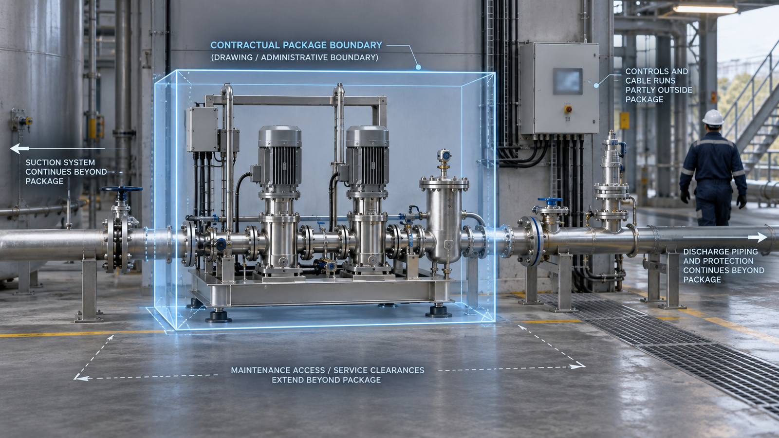
Battery limits are necessary, but they are not physical barriers
Battery limits define scope. They identify where a supplier’s responsibility, piping, wiring, controls or mechanical package begins and ends. Without them, contracts and drawings become vague.
The difficulty starts when a commercial boundary is treated as if loads, pressure waves, heat, vibration, contamination, control signals and human actions stop at the same line. They do not.
NASA’s systems-engineering guidance describes interfaces as physical, electrical, mechanical and human, and calls for both internal and external interfaces to be defined and controlled. It also links interface information directly to integration, verification and validation.[1] Items that must work together need more than individually acceptable specifications.
The review boundary should therefore follow the mechanism under investigation, not simply the purchase-order boundary. That does not mean reviewing an entire factory every time. It means extending the review far enough to capture the conditions that can materially alter the decision.
Commercial boundary
Defines responsibility, scope and the point where supplied systems connect.
Engineering boundary
Extends far enough to capture conditions capable of changing the decision.
Start with the duty, not the component drawing
A component drawing can confirm dimensions, materials, tolerances and local load paths. It cannot, by itself, establish the complete duty.
The wider review should define at least:
- normal operating points and expected variation;
- start-up, shutdown, standby and changeover conditions;
- maximum and minimum pressure, flow, speed and temperature;
- fluid properties and credible changes in composition or viscosity;
- upstream and downstream restrictions;
- control philosophy, alarms, trips and operator interventions;
- cleaning, flushing, draining and isolation duties;
- maintenance states and foreseeable incorrect operation;
- environmental conditions, utilities and loss-of-utility cases;
- the consequences if a safeguard or neighbouring item fails.
For machinery supplied in Great Britain, current government guidance on the Supply of Machinery (Safety) Regulations describes an iterative risk-assessment process that begins by determining machinery limits, including intended use and reasonably foreseeable misuse. It also refers to foreseeable abnormal situations.[3] The applicable legal route and latest requirements must be checked for the actual product and market, but the engineering lesson is broader: nominal operation is not the complete design envelope.
Interfaces are where assumptions collide
An interface is not merely a flange size or connector type. It is a transfer of load, energy, material, information or responsibility.
Mechanical interfaces
These include flange loads, baseplate stiffness, alignment, pipe strain, support positions, thermal growth, drive coupling behaviour and foundation response. A locally adequate casing can still distort if connected pipework imposes loads that were omitted from the assessment. A shaft calculation can be correct for the assumed bearing positions yet misleading if the installed support stiffness differs substantially.
Fluid and process interfaces
Suction pressure, downstream resistance, trapped gas, static head, recirculation paths, fluid temperature and viscosity all cross equipment boundaries. Positive displacement equipment adds a particularly blunt reminder: if flow continues into a blocked system, pressure will rise until something limits it. The protective route, control response and discharge system are therefore part of the behaviour, even when supplied by different parties.
Electrical and control interfaces
A motor, variable-speed drive and control system must agree about speed range, torque, acceleration, direction, trips and restart behaviour. The mechanical item cannot compensate for an incorrect minimum speed, aggressive acceleration ramp or control loop that repeatedly drives it into an unsuitable region.
Human and maintenance interfaces
Access, lifting, isolation, tool clearance, drainage and withdrawal space affect whether equipment can be maintained as intended. If a routine task requires an improvised lift, removal of unrelated pipework or opening a line that cannot be positively isolated, the installation has created a system-level weakness.
Review credible abnormal conditions without inventing fantasy scenarios
A wider review can become unhelpful if it degenerates into an unlimited list of imaginable failures. The aim is not to model every event in the universe. It is to identify credible conditions that can change the design decision.
Useful prompts include:
- What varies during normal production?
- What has happened on similar equipment or this installation?
- What single fault can remove an important safeguard?
- What happens when a valve is shut, a line blocks or a utility fails?
- What occurs during cleaning, priming, draining or product changeover?
- Can a local failure overload another component?
- Can an operator reasonably create an unsafe state while following an unclear procedure?
- What changes after wear, fouling, corrosion or repeated thermal cycling?
HSE guidance for plant modifications states that changes can affect plant quite remote from their source, so the relevant plant should be considered during hazard identification and risk assessment. It also calls for traceable safety, engineering and technical review covering process conditions, operating methods, safety, environmental conditions and engineering hardware.[2] That guidance is written for process plant change control, not every routine design review. It nevertheless illustrates why consequences should be followed beyond the altered item.
Useful boundary test
Does this operating change, single fault, human action or degraded condition have a credible route to alter the design decision?
A practical system-boundary review sequence
The following sequence is deliberately simple. The depth should be proportionate to the duty, uncertainty and consequence.
Write down what the review must decide. Examples might be whether a design can proceed to manufacture, whether an installation is suitable for a new duty, or which evidence is needed before increasing speed.
A review without a decision tends to collect observations without resolving anything.
Create a simple diagram showing the item, upstream and downstream equipment, supports, drive, instruments, controls, utilities, safeguards and operator interactions. Mark the contractual battery limits, but do not stop the diagram there.
Keep them separate. A specified fluid temperature is a fact only if the source is controlled and applicable. An estimated maximum viscosity is an assumption until supported. An unknown relief-valve setting is missing information, not permission to select a convenient value.
For each interface, identify what crosses it:
- force and moment;
- torque and speed;
- pressure and flow;
- heat;
- electrical power;
- commands, feedback and trips;
- material, contamination or cleaning fluid;
- human action and responsibility.
NASA’s interface-management process recommends capturing interface requirements, boundaries, responsibilities, changes, decision rationale and assumptions in controlled documentation.[1] A smaller industrial project may use a compact interface register rather than a formal interface control document, but the record still needs an owner and a method of change control.
Include the nominal case, expected extremes and a limited set of credible abnormal cases. For each case, ask what loads arise, which protective measures are required and whether the evidence supports the assumed response.
Do not stop at “component fails”. Ask what happens next. Does flow stop safely, pressure rise, containment fail, product contaminate, a drive trip, or an operator enter a hazardous maintenance state?
This is not automatically a formal HAZOP, FMEA or statutory risk assessment. Those methods require explicit scope, suitable competence and the correct participants. The review should state clearly when a specialist safety study is required rather than implying that a design checklist replaces one.
The next step might be an inspection, hand calculation, supplier clarification, instrumented test, tolerance review, CFD or FEA. Use the smallest method capable of resolving the decision, but do not use simplicity as an excuse to ignore a load-bearing uncertainty.
Record each important action, responsible party, acceptance criterion and evidence required for closure. Interface requirements also need change control because a late change on one side can invalidate work already completed on the other.[1]
Conceptual example: a pump package that passes locally
Consider a pump package selected for the required nominal flow and differential pressure. The pump, coupling, motor and baseplate calculations are satisfactory.
A component-only review might stop there. A system review would ask:
- Is the available suction pressure sufficient at maximum viscosity and flow?
- Are suction losses based on the actual pipe bore, fittings and fluid temperature?
- Can the discharge be isolated while the pump runs?
- Where is pressure relief provided, and where does relieved flow return?
- Is the minimum continuous speed compatible with the control strategy?
- Can the baseplate remain aligned after grouting and pipe connection?
- Does the installed arrangement permit venting, draining, cleaning and seal access?
- What happens after a power interruption or automatic restart?
The example does not prove that the package is unsuitable. It shows that local compliance is only one part of system suitability. The outcome may be no design change at all, but that conclusion is stronger when the interface assumptions are visible and checked.
What a proportionate review should produce
A useful output does not need to be a hundred-page report. Depending on risk and complexity, it may contain:
- the decision and scope;
- a system-boundary diagram;
- operating cases;
- an assumptions and evidence register;
- interface requirements and owners;
- significant failure paths;
- calculations, inspections or tests required;
- findings ranked by consequence and confidence;
- explicit exclusions and specialist-study triggers;
- closure criteria and approval responsibilities.
The point is traceability. A reviewer should be able to see why the boundary was chosen, which conditions were considered and what evidence supports the recommendation.
The test is traceability
Can another engineer see why the review boundary was chosen, which conditions were considered and what evidence supports the recommendation?
Look beyond the line on the drawing
Battery limits remain useful for defining supply and responsibility. They are poor substitutes for an engineering system boundary.
A sound review follows loads, energy, material, information and human actions far enough to understand the real duty. It separates facts from assumptions, examines credible abnormal conditions and closes important interfaces with evidence. Sometimes that exposes a serious omission. Sometimes it confirms that the original design is reasonable. Both are useful outcomes.
Ekyos welcomes consultancy enquiries about structured mechanical and fluid-system problem definition, engineering diagnostics and design review. A first conversation can establish the decision, available evidence and whether a bounded review is appropriate. It does not imply certification, statutory approval or immediate availability of every specialist analysis service.
Review the system that creates the duty
A bounded review can expose interface assumptions, missing evidence and credible failure paths before they become installation problems.